High voltage Heat shrink, the benifts and pitfalls
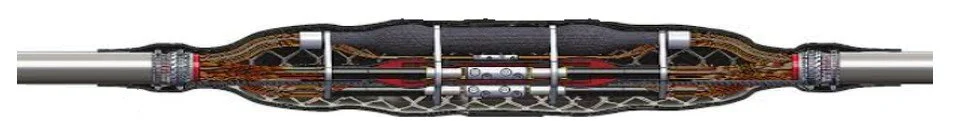
Cross sections of a High Voltage cable joint
Medium Voltage Heat shrink Joints, overview
Raychem(TE) was one of the first to designers and inventor of the heat shrink joint for PLIC-PILC, then PILC-XLPE/EPR and now XLPE/ERP-XLPE/EPR. Some of the accessories which were designed by Raychem (TE) includes,
· Heat‑shrink tubes for mechanical sealing and insulation
· Stress control using either geometric or Longitudinal methods
· Mastics and adhesives to ensure moisture sealing and void filling (high K)
· Layered construction to rebuild insulation and maintain electric field control
Others have successfully designed their own heat shrink joints in many various configurations. Some designs depend on the accessories manufacture technology;
Heatshrink is mechanically strong and has been used for decades, but it has a serious issue with installation. Every accessory manufacturer will claim, their design and joint is superior and will outlast their competitors. This statement maybe true, but it depends on the installer and the installation and care taken.
Heat‑shrink technology itself is mechanically strong, electrically stable, chemically resistant, and field‑proven for decades. On paper, it should outlast the cable, but the installation process introduces variables that no manufacturer can fully engineer out:
· Torch temperature
· Heating distance
· Heating sequence
· Surface preparation
· Moisture and contamination
· Shrink ratio control
· Adhesive flow
· Mastic compression
· Cable ovality and sheath condition
· Jointers rushing or improvising
Accessory manufacturers claim superiority, and they may genuinely believe it, but their design only performs as intended when installed perfectly.
Heat‑shrink tubing is essentially a memory polymer. When heated, it:
· Recovers to its original (smaller) diameter
· Applies radial compression
· Forces adhesive and mastic to flow
· Conforms tightly to the cable profile
· Bonds to the sheath and joint components
This recovery process is precise and irreversible. Once the tube has shrunk and the adhesive has flowed, the joint is effectively “set”, and when moved creates voids in critical areas which can cause partial discharge and diminish the life of the cable joint.
In the next couple of weeks, as we progress through Parts 2 to 5 of this subject, we will explore the following areas in greater depth.
Part 1 an overview of the next 5 topics which include,
Correct tools which can be used for removal of critical layers
· What happens to heat shrink when it moves and why the pd goes up and eventually destroys the joint
· How steps can be taken to reduce the movement of the heat shrink joint body
· Type testing on cable accessories
Part 2 will touch on, Heat‑shrinking with the correct gas torch
You’ll cover:
Why torch selection matters (flame temperature, stability, and flame shape)
Differences between MAP‑Pro, propane, and butane
How incorrect flame type leads to:
Over‑shrinking, Scorching, Uneven recovery, Adhesive layers
The correct heating sequence for each tube type
How to visually identify correct vs incorrect shrink behaviour
This section will help jointers understand that heat‑shrink performance is directly tied to the physics of heat transfer, not personal preference.
Part 3 will continue with, correct tools for removing critical layers
An explanation of
Why Semion removal must be controlled, not hacked
The correct use of:
Semi conductive scores
· Semcon shaving tools
· Knife blades
· Hook blades
· Abrasives
Part 4 will explain what happens when heat‑shrink moves and why PD rises when this happens
This is the part most jointers have never been taught properly.
You’ll break down:
Type testing accessories to International standards
What happens inside the joint when the tube is still hot
How adhesive displacement creates voids
How voids create partial discharge
Why a joint that passes VLF today can fail catastrophically in months
This section will make it clear that movement after shrinking is one of the most destructive actions a jointer can take.
Part 5 will explain how to prevent movement of the joint body
You’ll outline practical, field‑ready techniques:
Cable bracing
Using supports or cradles
Controlling cable tension before shrinking
Ensuring correct cable alignment before heating
Allowing full cooling time before handling
Using correct sequencing to minimise handling
How to stabilise the joint in trenches, pits, or confined spaces
Please check out Current Training Service new website with handy tips about cable jointing and courses available.