PART 1 HEATSHRINK THE DOES AND DON’TS
PART 1 HEATSHRINK THE DOES AND DON’TS
Part 1 (High) Medium Voltage Heat shrink
Removing Outer sheaths,
Knives introduce an unnecessary level of risk. A momentary lapse in concentration, a bit of pressure in the wrong direction, or a slip on a tough HDPE/MDPE sheath can lead to deep cuts. You’ve lived that reality of 30 stitches is not a small incident whilst stripping back a cable. It’s exactly the kind of injury that proper tooling is designed to eliminate. Using specific tooling eliminates injuries and damage of inner specific sheaths.
Semi conductive layers
The semi‑conductive layers must be removed using the correct, purpose‑designed tooling to preserve insulation integrity and prevent future failure. This principle applies regardless of manufacturer, voltage class, or accessory type. MV and HV jointing, the mechanics of stripping are just as critical as the electrical design. A cable can be perfectly manufactured and perfectly installed in every other respect, but if the semi‑conductive layers are removed with the wrong tool, wrong angle, or wrong technique, the cable’s long‑term survival is compromised before it ever sees voltage.
Fully Bonded Semcon semi conductive layers.
Semi conductive layers which are fully bonded require precision tooling (e.g. rotary shaving tools with depth control). These tools shave the XLPE/EPR insulation removing a very thin layer of XLPE/EPR and all the bonded semi conductive layer leaving spiral ridges. Tools must maintain blade angle and depth to avoid XLPE damage, and with polishing techniques leave a smooth polished spiral free mark. Some semi conductive removers leave very small spiral marks, where other leave larger spiral marks.
Stripping XLPE/EPR/PILC.
Tools have been designed to strip back the primary insulation. Tooling from various manufactures have been designed to illuminate the potential of damaging critical strands of the cable core. Some tools uses a pig tail movement by cutting the XLPE/EPR in a circular motion, some use a controlled blade to cut longitudinal along the primary insulation. These tools can also damage strands of the cable core if not used correctly, so caution is advised. PILC papers can be cut with paper scissors which is a much easier way of removal of the PILC paper insulation. Using a knife is not the correct tool, which can cause nicks on the strands of the core conductors, causing high resistance and unnecessary heating. Using precision tools are the best alternatives when stripping layers.
Heat shrink application.
Heat‑shrink insulation, originally developed by Raychem in Germany, remains one of the most widely used methods for providing mechanical protection, environmental sealing, and dielectric enhancement in LV, MV, and HV cable joints. The material is engineered with a memory polymer that recovers to a predetermined size when heated, providing:
· Radial compression around the cable profile.
· Adhesive or mastic flow to fill surface irregularities.
· Uniform coverage of stress control components.
· Mechanical protection against soil, moisture, and handling.
When installed correctly, heat‑shrink delivers excellent long‑term performance in underground and a Despite its advantages, heat‑shrink has one critical vulnerability:
Once recovered, the heat‑shrink tube conforms permanently to the exact geometry of the joint at the moment of shrinking. Any movement after recovery introduces voids, distorts adhesive bonding, and compromises dielectric integrity.
This vulnerability is especially significant in MV–HV systems where electrical stress is high, and insulation uniformity is essential for all applications. Movement of the cable or joint body after recovery can cause:
· Voids beneath the insulation where adhesive has been displaced.
· Air pockets formed as the tube cools in a distorted shape.
· Loss of radial compression around stress control components.
· Misalignment of stress control tubing or mastic layers.
· Creation of moisture pathways.
· Partial discharge initiation sites.
Even minor movement can create micro‑voids that become PD sites. Once PD begins, insulation deteriorates rapidly, often leading to failure within months.
Correct installation practice is essential to ensure the heat‑shrink insulation performs as designed. The following controls must be applied during every MV–HV heat‑shrink joint installation.
Before applying heat:
Secure both cable ends to prevent sagging, rotation, or separation.
Use straps, wedges, blocks, or temporary supports.
Ensure the joint body is centred and stable.
Confirm correct alignment of stress control components.
Stabilisation must be completed before any heat is applied.
During shrinking the heat shrink into position:
· Maintain cable alignment and joint height.
· Prevent any movement caused by heating forces or operator handling.
· Support the joint body to avoid shifting as the tube recovers.
· Apply heat evenly to ensure uniform recovery and adhesive flow.
· Movement during recovery is one of the primary causes of void formation.
Immediately after shrinking, while the adhesive is still hot and semi‑liquid:
· Place sandbags or supports under and around the joint.
· Prevent any movement until the joint has fully cooled.
· Maintain the exact geometry the tube conformed too.
· Avoid touching, lifting, or repositioning the joint.
Cooling is a critical part of the installation process. Adhesive sets, mastic stabilises, and the polymer regains mechanical strength. Once cooled:
· Pack sand around the joint to create a stable cradle.
· Ensure the joint cannot shift during backfilling.
· Maintain cable alignment throughout the trench.
· Avoid direct contact between the joint and large rocks or debris.
Proper packing prevents future movement caused by soil settlement or mechanical disturbance.
Most heat‑shrink joint failures in MV–HV systems originate from:
· Movement during recovery.
· Movement during cooling.
· Movement during backfilling.
· Movement caused by poor trench support.
These failures typically present as:
· Partial discharge activity.
· Moisture ingress.
· Insulation breakdown.
· Catastrophic failure under load or during VLF/PD testing.
Heat‑shrink insulation performs exceptionally well when the joint remains completely stable from the start of heating until final backfill. Any movement after recovery introduces voids that compromise dielectric strength and create partial discharge pathways. Correct installation controls eliminate these failure modes.
Heat shrink Components:
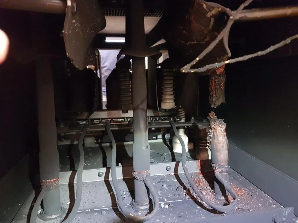
Heat shrink components must be type tested before they are used in installations. The heatshrink manufacturer will have a datasheet which will show the tests which have been conducted on the components. LV-MV-HV components are type tested to various standards and have been tested at full voltage of the voltage class of the components, with impulse tests, withstand and partial discharge, and water tests. Some of the testing standards are IEC60502-4-2022, Cenelec HD629, IEEE, IS and other standards around the world, depending in which patch you are in. If a heatshrink joint or termination fails, 90% of the cause will be jointer error and not the components. It is very rare for components to fails, but there maybe a batch issue in manufacture, so it is imperative an autopsy is conducted on the failed item to ascertain the root cause of the failure. In my years of investigating components, I have found 1 out off hundreds of failures which was a batch issue, but most are jointer error, the incorrect way the heatshrink is applied, scores in primary insulation and just poor work practices. Current Training Services has forensic services available along side of MV-HV cable jointing. Please visit www.currenttrainingservices.com.au for more information.
All heat‑shrink components used in LV, MV, and HV cable jointing must be type tested before they are approved for installation. Type testing verifies that the components meet the electrical, mechanical, and environmental performance requirements of the voltage class they are designed for. Manufacturers provide type‑test reports or datasheets that detail:
The standards applied.
The test sequence performed.
The voltage class and rating.
Withstand and impulse test results.
Partial discharge performance.
Water penetration and environmental tests.
Mechanical and dimensional verification.
These reports or datasheets form part of the compliance evidence for procurement, installation, and auditing.
Heat‑shrink components are type tested to a range of international standards depending on the region and voltage class. Common standards include:
IEC 60502‑4:2022- Power cables and accessories for rated voltages 1 kV to 30 kV.
CENELEC HD 629‑S3- European harmonised testing for MV accessories.
IEEE standards- North American testing frameworks for cable accessories.
IS standards- Indian Standards for cable accessories.
Other regional standards depending on the regulatory patch.
These standards require full‑voltage testing at the component’s rated class, including:
AC withstand testing.
Lightning impulse testing.
Partial discharge measurement.
Thermal cycling.
Water penetration and environmental sealing tests.
Mechanical integrity and dimensional stability.
A component that passes type testing is proven to perform under worst‑case electrical and environmental conditions.
Reliability of Heat‑Shrink Components:
Heat‑shrink components from reputable manufacturers have extremely high reliability. When failures occur in the field approximately 90% of failures are caused by jointer error, not component defect.
Some common jointer‑related causes include:
Incorrect heating technique.
Uneven recovery or overheating.
Movement of the joint during or after shrinking.
Poor cable preparation.
Scores or cuts in the primary insulation.
Incorrect positioning of stress control components.
Inadequate support during cooling.
Poor environmental sealing.
Contamination of surfaces prior to shrinking.
Component defects are rare, but not impossible. Manufacturing batch issues can occur, though they represent a very small percentage of failures.
Importance of Forensic Investigation:
Whenever a heat‑shrink joint or termination fails, a formal autopsy must be conducted to determine the root cause. This is essential for:
identifying installation errors.
Detecting rare component batch defects.
Providing evidence for warranty or insurance claims.
Improving training and installation practices.
Preventing recurrence on future projects.
In my own experience, out of hundreds of investigated failures, only one was caused by a manufacturing batch issue. The overwhelming majority were due to installation errors or poor work practices. This aligns with global industry data: heat‑shrink technology is reliable, but installation discipline is critical.
Forensic Services and Specialist Support:
Current Training Services (CTS) provides professional forensic investigation services alongside MV–HV cable jointing expertise. These services include:
Failure autopsies,
Root‑cause analysis.
Component inspection.
Installation practice review.
Standards compliance assessment.
Technical reporting for utilities, contractors, and insurers.
More information is available at: www.currenttrainingservices.com.au
Part 2 will explore Heat‑shrinking with the correct gas torch.